How we touched a chosen balloon with a pushpin without popping it.
We always talk about how nice it is to have fully integrated 2D and 3D data. How much we appreciate that our 3D point clouds come with full RGB images. Once you find the pixels that describe your feature in the 2D image, you can directly correlate it with the 3D data at the same pixels. Since all this information can be given by the Zivid camera, one device is all you need to see your workspace in full definition.
Having all the scene information delivered from the same sensor simplifies the total setup of your system. For example, there is no need to calibrate an external 2D color camera to the same coordinate frame as your 3D camera. This also makes the task of robot mounting straightforward, allowing you to get all the information you need and have imaging flexibility in your environment. Being able to place your camera dynamically allows you to get the best imaging position for your scene.
We want to prove this to you, put our money where our mouth is if you will. Let us show you a fun way to explore the usefulness of color data in combination with high-quality 3D point clouds. What better way to do this than to touch a balloon with a stick pin and not pop it? Lots of color, a few loud noises and now you got a party! Here is the point cloud:
Watch full webinar "Point Cloud Trueness: the secret to reliable picking".
Step 1: Building the detection
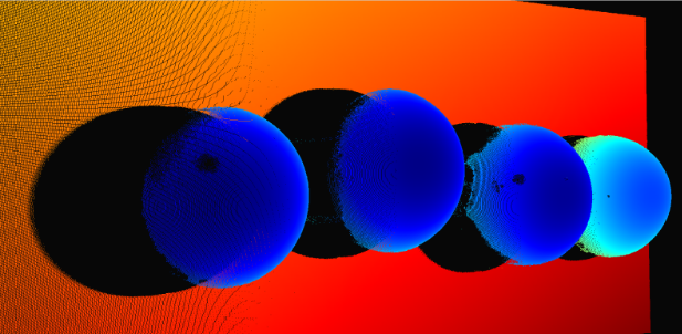 Figure 1: Point cloud of balloons with depth coloring
To start building our system we will focus on the detection aspect. The first goal is finding the balloons in the 2D image. We are not trying to build a full detection algorithm for this task but go with a rather basic approach of examining the color values in the scene. Each pixel in the scene has an assigned R, G, B value. Each of these will have a value between 0-255 and comparing these values can indicate which color a pixel has. This is a rather crude method, but acceptable for our quick setup. The color values should distribute as expected:
- Red: R > 200, G < 50, B < 50
- Green: R < 80, G > 200, B > 60
- Blue: R < 10, G < 80, B < 100
- Yellow: R > 200, G > 200, B < 50
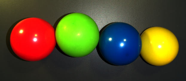 Figure 2: 2D color image of the four colors of the balloons.
For our set up the background has been either black or grey, which is rejected by the above conditional statements. One statement is chosen and then the Boolean logic allows us to create a binary mask that will be the same size as the original image. The 1 values will indicate the area where the conditional statement is true, and the 0 where the color is false, this is shown looking for the blue balloon below.
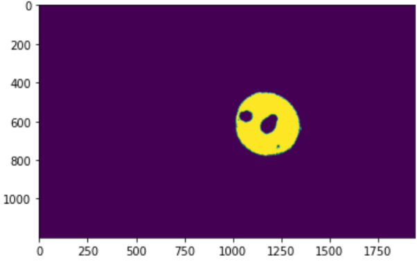 Figure 3: Bit map of the area where the blue values were found in the capture.
Using OpenCV we can do some edge detection on the bitmask and find the outline of the biggest yellow section and fill it in, showing where we found the surface of the balloon. This area is where we will look to find the position of our target point. The next step will be to find the correct approach orientation.
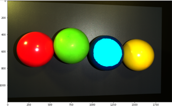 Figure 4: 2D image with cyan coloring the surface of the balloon that is detected.
With the data that Zivid provides, we can find out a lot of information about every point in the point cloud without doing any additional work on our side. Now that we have the XYZ location of the point we want to touch, we can find approach orientation for that point. For this, we can use the surface normal vector that is provided from the Zivid SDK and use it as the Z-axis of the target orientation to create an approaching target that we can drive the robot to. A crucial part to keep in mind for this step is the X and Y orientation of the target that the robot will be approaching.
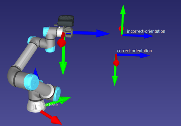 Figure 5: Simulation capture showing two different pose orientations around the Z-axis.
For our case, the best practice is to align the X and Y orientation to be similar to the robot in its current position and orientation. This allowed us to keep the camera on the upper side of the wrist joint and decrease the risk of causing cable strain or any collisions with the robot. Since the camera is parallel to the floor it was possible to reference the camera coordinate system to help define the X and Y vector for the touch pose.
A point is selected to the side of the pick point to help define a helping vector for defining the pose. We can then normalize this vector and use it to define the y vector using the cross-product of the helping vector and the Z vector. Now that we have a Y and Z vector that are perpendicular to each other, we can use those to find the final X vector for our pose by cross product. With these three vectors, we can define the rotational matrix of our 4x4 homogeneous transform.
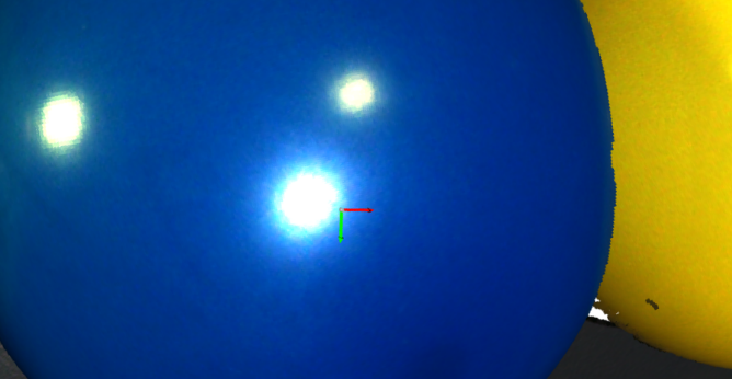 Figure 6: Screenshot of visualization of target pose on 3D render
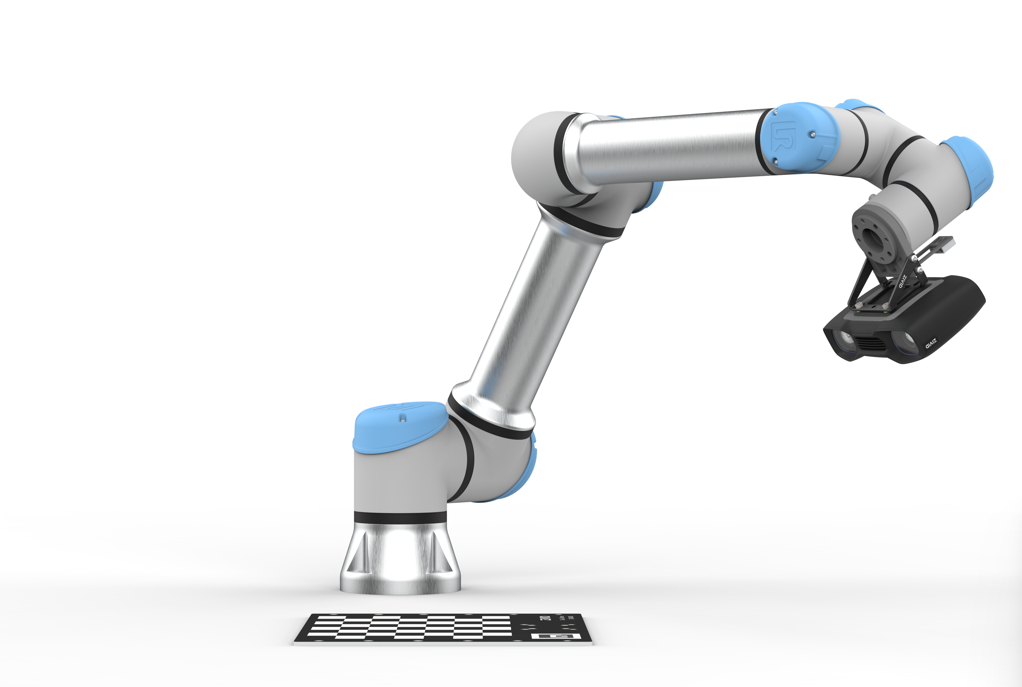
Step 2: Hand-eye calibration
A topic that will never go out of style is performing hand-eye calibration. To get the best accuracy from your system finding the transform from camera frame to end-effector frame by using hand-eye calibration is absolutely necessary. Any small angle or change when mounting can cause dramatically different outputs from the CAD drawings. Zivid has API support as well as a CLI tool that can be used for performing hand-eye for both eye-in-hand and eye-to-hand setups. The calibration target that is used in this exercise is the ZVD-CB01 calibration target. This target is used for both hand-eye and infield correction. For the best performance out of your setup, it is recommended to perform infield correction before performing hand-eye calibration.
Important! Every time a camera is bumped, knocked, or removed from the position where hand-eye was performed, hand-eye must be performed again. Micrometers of movement or a change of fractions of a degree in the mounting connection can dramatically change the hand-eye transform. For this reason, it is important to adhere to the recommended tightness guidelines for the Zivid mounting hardware provided in the datasheet.
Step 3: Using hand-eye calibration
The transform that is returned from hand-eye calibration is in the form of a 4x4 homogenous transform matrix. This is the format that we will use for all our transformations in our math for this project. The hand-eye transform can be multiplied with the pick point 4x4 matrix to transform the point location into an end-effector frame, this can then be transformed into a robot base frame by multiplying it with the pose of the robot, also as a 4x4 transform. This places the point the TCP (tool center point) needs to move to into the base frame where the robot can then be driven to this point. And with that, you have a balloon-touching robot!
With the Zivid camera, the task is simplified to find and target what is important to you in your environment. One of our main goals is, to be as user and developer-friendly as possible. If you have any other questions about how to interface with the Zivid SDK, check out all our samples on Github as well as the resources on our Knowledge Base.
If you want to know more about trueness and its impact on your robot cells, read our technical paper about trueness:
- Part 1: I Can See it But I Can't Pick it: Why Trueness is the Secret to Reliable Picking
- Part 2: Precision and Trueness: Seeing the Details and Remaining True to Reality
- Want to go further? This is a sample of our white paper "Achieving accuracy in vision-guided robotics". Read it here:

We will continue to provide more information and material to support the integration of Zivid technology into your systems. Quick to integrate, ease of use, and high-quality data is a priority at Zivid so we can simplify your detection needs.
Let us know what types of materials you want to see next!
Achieve Optimal Hand-Eye Calibration for Enhanced Robotics Performance
The practical guide to 3D hand-eye calibration with Zivid One+