In the first part of this blog series, we set the scene with a little bit of background and history around how the three key components of 3D vision, accuracy, precision, and trueness required clearer definition so we can better assess 3D camera technology. In this, the second installment, we look deeper into what makes up precision, the seeing of the details, and trueness, the closeness to reality.
This is a sample of our white paper "Understanding accuracy in vision-guided pick and place". Read it here:

Table of content
- Seeing the details: precision
- See tiny objects and minute details
- Precision illustrated
- Trueness: "true to reality"
- True to reality point clouds for more accurate and reliable grasping and manipulation
a. Other sources of trueness error in a robot cell
b. Stiff grippers and metal objects - little margin error
c. Grippers with more tolerance - Absolute position and "a true reference"
a. The 3D camera origin
b. Standardization on relative measurements for verification
c. Hand-eye calibration - bringing "absolute back into the relative
Seeing the details: precision
When you measure a surface 3D point it will always have some variance in comparison to previous measurements. Even if all measurement conditions are kept constant, there will be a shift from measurement to measurement. This phenomenon is unavoidable due to random noise effects.
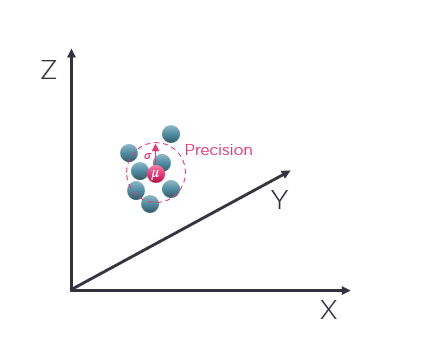 Fig 1: A single surface point in space measured over time, showing the expected position (mean) and the variability between repeated measurements (precision)
The average value (mean value) of a set of repeated measurements will be where your 3D vision camera expects that a measured point is in space and the standard deviation would be the system's precision. Precision represents the general term for variability between repeated measurements and tells you the certainty that a measurement point will be within a certain distance range from a measured 3D point coordinate (XYZ). It follows that the calibration and physical state (thermal/mechanical) of the 3D camera will dictate how close this expected coordinate is compared to where it actually is in the physical sense (more on that under the Trueness section). Therefore, precision is the measure of the variation caused by a random error (or local high-frequency noise) in your measurement. The closer the measured points are, the better your precision. The further apart they are spread, the lower your precision.
See tiny objects and minute details
Precision is affected by the local variability (surface noise) and is the main specification by which we judge a system’s ability to see small details on a surface. It will give an indicator as to the kinds of fine details you can pick out from your point cloud. It may be details such as the 2 mm diameter head of a small screw or bolt, a piece of wire, or a gap between tightly packed boxes that is just a few millimeters across. These are the questions that a 3D system’s precision and spatial resolution in general help to answer. Considering other characteristics also come into play such as the object’s material type and surface, its reflectivity, or absorptive qualities.
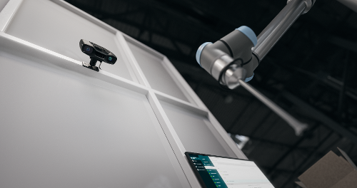
It is important to remember that precision specifications are highly dependent on viewing distance and the focus distance of the chosen 3D camera. This is a critical consideration when deploying a 3D camera, that it is working within the correct operating distance range. This is a particular benefit of adopting the on-arm paradigm, where the 3D camera travels with the robot arm. This approach allows us to move to an optimal viewing distance to achieve the best precision possible in variable situations.
Zivid 3D cameras offer best-in-class precision across their working distance. With any such system once you move beyond the bounds of its recommended working distance then precision deteriorates quite rapidly.
Below are two graphs. A comparison of precision as a function of the width of the field of view of the Zivid One+ and Zivid Two camera models and an exemplified scenario showing the precision and spatial resolution with Zivid Two imaging a 60 x 40 x 40 cm bin.
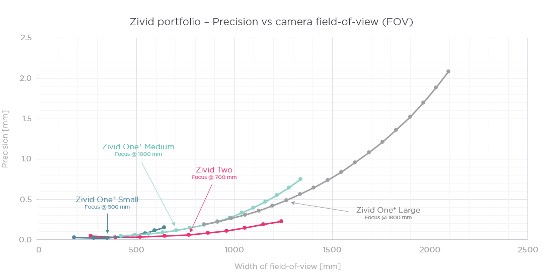 Fig 2: precision characteristics for Zivid One+ and Zivid Two 3D color cameras
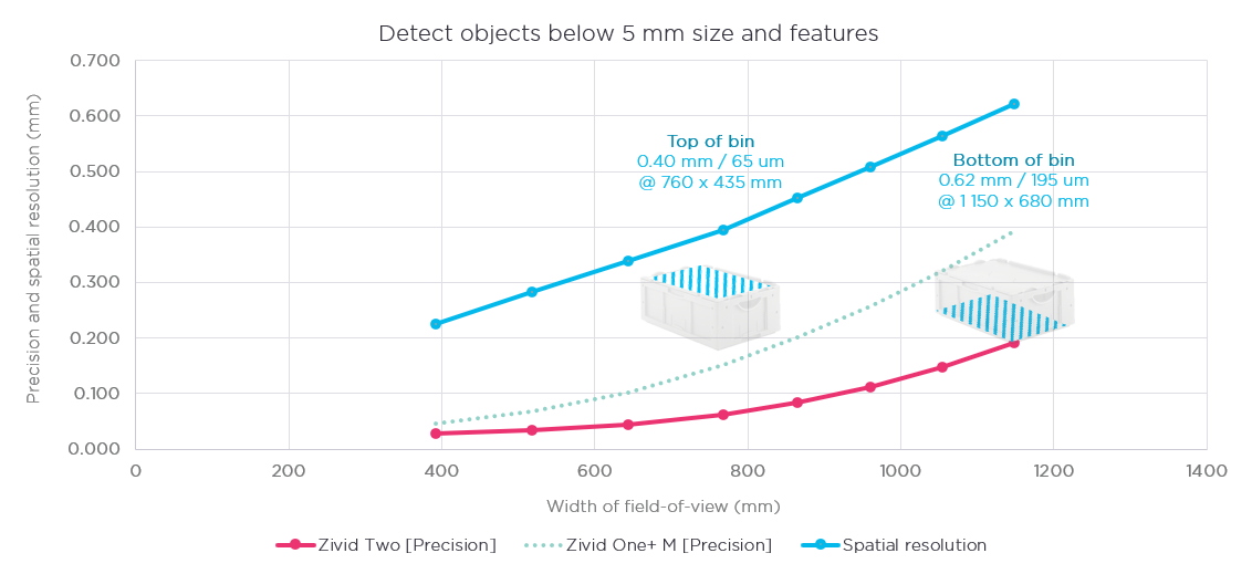 Fig 3: precision and spatial resolution for the Zivid Two 3D camera compared to Zivid One+ Medium
In the plot the top of the bin can be seen approximately at 700 mm (the focus distance) where the visible FOV is 760 x 435 mm, the spatial resolution is about 0.4 mm, and the precision 0.065 mm. The bin is 40 cm deep, so the bottom of the bin would be at 1100 mm, where the FOV is 1150 x 680 mm, spatial resolution is 0.62 mm, and precision 0.195 mm.
Precision illustrated
To illustrate what these numbers mean let’s look at a point cloud of a machined plate captured with a Zivid Two 3D camera. The plate has several holes with accurately machined diameters and depths, from 5 mm to 20 mm in diameter (Ø) and from 0.25 mm to 5 mm in depth (D).
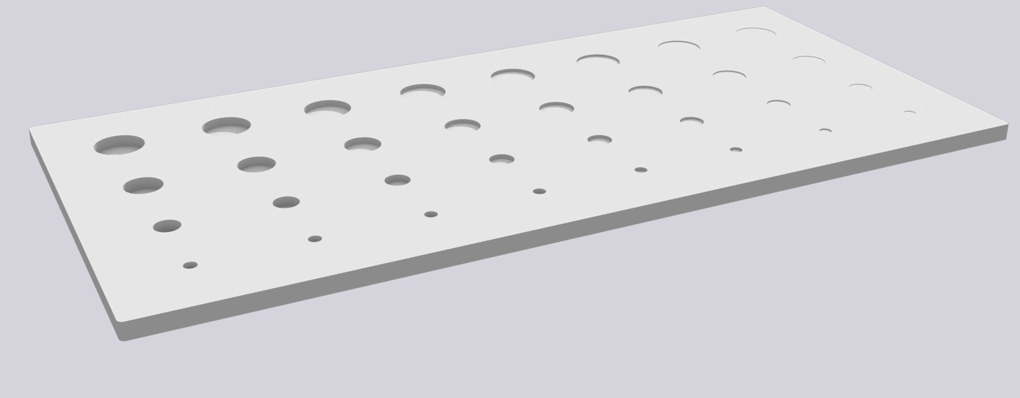 Fig 4: Model of the machined plate with associated dimensions
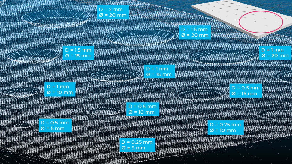
Fig 5: point cloud of one side of the machined plate, showing the shallowest holes from D = 0.25 to 2 mm.
Individual points and small variations on the surface can clearly be seen
To illustrate further, let’s also look at some “everyday objects” captured with Zivid Two. The point cloud illustrates the impact of precision and spatial resolution and should give an indication of what sort of features should be possible to detect.
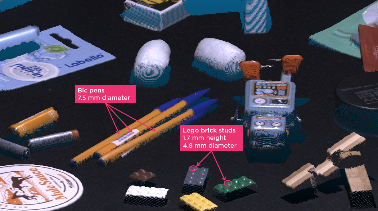 fig 6: Zivid Two's point cloud taken at 700 mm of some "everyday objects"
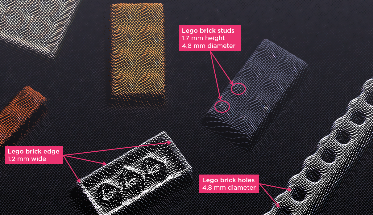
fig 7: close up on Lego bricks
Trueness - "True to reality"
Trueness is referred to as a lack of bias, defined as the difference between a measured value obtained from multiple repeated measurements (the expected value), and the true reference value of the parameter being estimated.
Watch our full webinar about "point cloud trueness, the secret to reliable picking".
If we consider a 3D point in space that we have measured repeatedly and now gives us a small local cloud of points that are potential positions for where we believe this point is located on the surface of an object. Imagine now that you have an exact reference point of where this point is located, a true reference position. In Figure 8 the system trueness is thus represented by the distance between the expected position, the average of your repeated measurements (the red point), and the actual true reference point (the green point). The precision is the variability of these measurements. The trueness error is the deviation from a true reference.
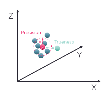 fig 8: the expected position (mean) given a set of of repeated measurements compared to the true reference position where the point is in physical sense
‘True to reality’ covers the concept very well. For 3D point clouds, trueness means the correct representation of an object’s form and dimensions, its rotation and position, and any warping or skewing from ‘the truth’.
An illustrative example is shown in Figure 9. If we are concerned with the true representation of the form of a perfectly flat surface, how planar is the surface when captured as a 3D point cloud? The high-frequency noise on the surface would be your precision, and the low-frequency systematic deviations, deformations, or misrepresentations would be the trueness. These two combined, yield the system’s accuracy.
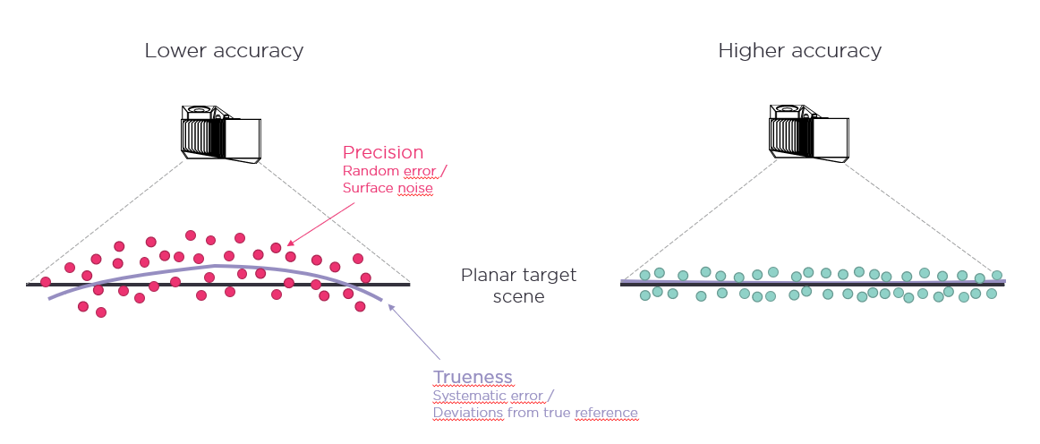
fig 9: precision and trueness and their causal errors
Another example is shown in Figure 10 where we have two accurately machined gears. If we imaged one of these gears and then measured the point cloud dimensions and compared them to the actual physical measurement of the gears, any difference tells us the trueness error of the system. So, if the gears are 100 mm in diameter and the 3D camera has a trueness error of < 0.2%, then we know the expected error in the measuring of the diameter will be 100 mm * 0.2% = 0.2 mm (200µm).
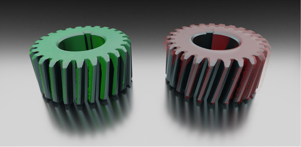 fig 10: low trueness error (green) and high trueness error (red) on machined gears.
There is a clear error in position, rotation, and scaling.
True to reality point clouds for more accurate and reliable grasping and manipulation
The automation of picking objects involves three key stages which are heavily dependent upon the performance of the vision system and robot cell:
- Detecting and localizing an object
- Correctly picking the object as expected
- Placing the object as expected
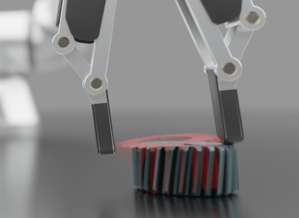 fig 11: trueness error affecting grasp point with stiff gripper
Clearly, the ability of the camera to see objects as they are in reality is fundamental to these operations being carried out successfully.
In real-world terms, this equates to how many millimeters of error or uncertainty should be accounted for between the calculated pick pose for the actual interaction of the robot gripper and the object. An unacceptably high trueness error will be felt at the picking stage and at the placement stage with errors in the first influencing errors in the second in a compounded manner.
Other sources of trueness error in a robot cell
Whilst the 3D camera is critical to the overall accuracy of a robot cell, it isn’t the only element that can introduce trueness errors and thus mistakes. Figure 12 shows the major component parts of a robot cell and their contribution to errors.
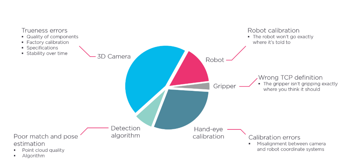
fig 12: elements of error contribution budget in a robot cell.
3D camera and detection
The 3D camera will account for inaccuracies in the detection together with the associated detection algorithm. We rely on a performant algorithm, but the algorithm will only perform as well as the 3D point clouds it must work with.
Watch our full webinar about "point cloud trueness, the secret to reliable picking".
The robot
Robots will have some margin of inaccuracy given a certain movement. Robot suppliers typically specify repeatability, which is the robot’s version of precision. Trueness is not specified for robots, and errors here, even for an industrial robot, may be orders of magnitude greater than any precision error. Trueness errors of a couple of millimeters are not uncommon.
Tool center point (TCP)
This is the interaction point between the robot’s tool flange and the gripper or end effector. This must be calibrated correctly and must remain solid or there will be an offset that must be added to the mismatch budget.
Hand-eye calibration
It is essential that the world of the camera and the robot are well correlated. This is known as hand-eye calibration. A good hand-eye calibration will give sub-millimeter correlation in small to medium workspaces such as bin-picking, with millimeter range correlation over larger areas for example in the case of depalletizing. The best hand-eye calibration results from updated or adapted calibrations for different regions of interest or changes in environmental conditions.
Stiff grippers and metal objects – Little margin for error
When we have a rigid gripper and rigid objects such as the steel gear, if the trueness error is too large the gripper will miss by a few millimeters. This seems small but will likely result in one of the following:
- A missed pick altogether
- An inaccurate, incorrect, unstable pick
- Damage to the gripper and/or the object
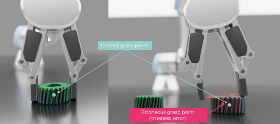 Fig 13: effect of large trueness error with stiff gripper and steel wrench heads
Grippers with more tolerance
With enough gripper compliance, some trueness errors can be mitigated. A suction cup gripper is a good example of this. The suction cup gripper has innate flexibility. However, there are scenarios where the flexibility is okay purely for the purpose of being able to pick an object. But that same flexibility means it is unlikely to have an accurate and firm grasp of the object. With heavier metallic objects the gripper can lose hold of the object during the robot’s kinetic motion and usually does not have the accuracy requirements demanded in assembly and machine-tending applications.
In assembly and some pick-and-place operations, there is a requirement for high-degree trueness at the pick and the place stage as both have little margin for error in terms of placement and positioning.
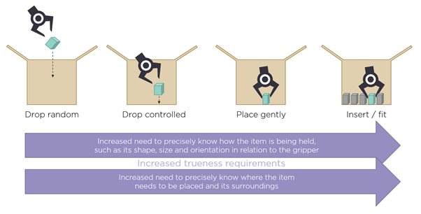
fig 14: critical trueness requirements at the pick and place phase of a task
Absolute position and "a true reference"
When evaluating a 3D camera's performance, what we ideally want is an absolute reference with which to compare the camera’s results. From there we can check for correlation in XYZ directions and get a level of confidence in the camera’s ability to detect points exactly as they exist in the physical world. The camera measures the distance from its internal origin to the objects in the scene of view as can be seen in Figure 15. So, if we knew the true reference distance exactly from some other means of measuring than the 3D camera itself, we could verify that the 3D camera measures the exact same distance.
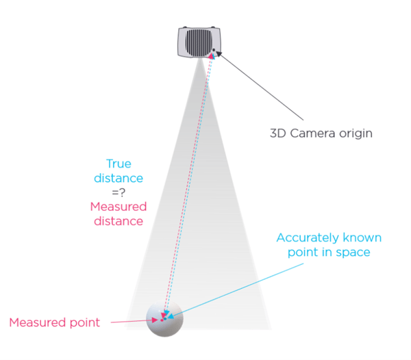
fig 15: illustration of absolute distance verification
Unfortunately, there are several challenges here. We are trying to verify the accuracy of a camera that resolves down to 100 micrometers; therefore, our means of verification probably should have a finer resolution that may be an order of magnitude or so better at say 10 micrometers. When we get down to these small measurements an awful lot of other factors come into play that we must be conscious of. If we are measuring on an aluminum jig at a distance of 1 meter and the ambient temperature changes by just 1 degree Celsius, the length of the distance between camera and object can change by 23.5 micrometers, already 2.3 x the reference accuracy we are hoping to use. So, getting an absolute reference we can say is unchanging and absolute is a challenge.
We would also need to locate the physical point and the 3D camera origin exactly, both in the real world for the reference distance measurement and in the 3D point cloud for the 3D distance measurement. Recognizing with high accuracy a physical point in the real world is possible but requires the use of a high-accuracy object/pattern for reference, such as a thermally stable meteorological reference sphere. However, determining a reference distance from such a physical point to the 3D camera origin is a different beast entirely.
The 3D camera origin
In an idealized camera model such as the pinhole camera model, the origin is the point where all light rays that enter the camera converge to a point also called the "center of projection". In this simplified model the origin is thus at the center of the aperture itself, it is the actual pinhole.
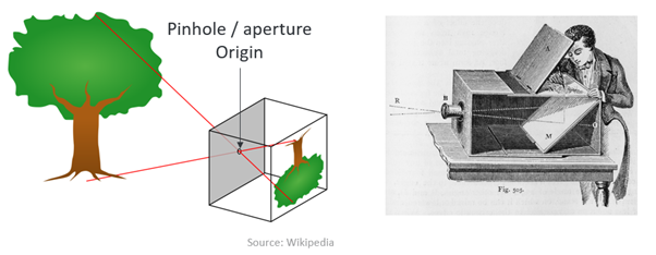 fig 16: pinhole/aperture origin
Since this is an idealized model, real cameras with lenses do not actually have a pinhole. But by analyzing images taken with the camera like what is done in-camera calibration, it is possible to calculate a pinhole model which models the real camera's optics very closely. The estimated pinhole aperture of this model, and hence the 3D coordinate origin, will be a 3D point somewhere inside the lens of the camera. Understandably, the exact point of origin in a camera's lens system is difficult to identify exactly and will have slight variations from camera to camera due to slight differences between the optics, mechanical tolerances, and the thermal state of each camera. The glass of the lenses and aluminum (or other materials) of the body would contract or expand depending on temperature, causing shifts in the location of this origin.
Watch our full webinar about "point cloud trueness, the secret to reliable picking".
Standardizing on relative measurements for verification
Without accurate physical reference knowledge of exactly where the 3D camera origin is in relation to other known physical structures in the real world, and all the challenges in measuring absolute, the only feasible solution is to use relative measurements for verification and performance characterization. Relative means relative to some external reference system (and not absolute in relation to the 3D camera origin) and we will cover this in detail in the next installment of this blog series. It is worth to note that this is also what the industry has turned to and how it’s represented in the already existing standards.
Hand-eye calibration – Bringing ‘absolute’ back into the relative.
So, a constant reliable absolute reference is difficult to achieve with a 3D camera in relation to the camera origin. For some situations, the absolute nature of our measurements is not as critical, for example, if we are trying to detect a hole in a car door panel, we can carry out the hole detection even if there is some slight positional error or rotational error (this is reliant on precision and spatial resolution). But when we want to accurately insert a bolt into the door panel’s hole (trueness) then we start needing some absolute references. In general, when a robot is going to interact with objects, manipulate, pick, grasp, insert, or assemble them, then absolute matters.
The answer here is finding the ‘absolute’ for our given circumstance, the robot, the gripper, and the 3D camera. Hand-eye calibration is the process of finding the best transformation between the robot end-effector and the 3D camera (eye-in-hand), or alternatively between the robot base and the world coordinate system (eye-to-hand).
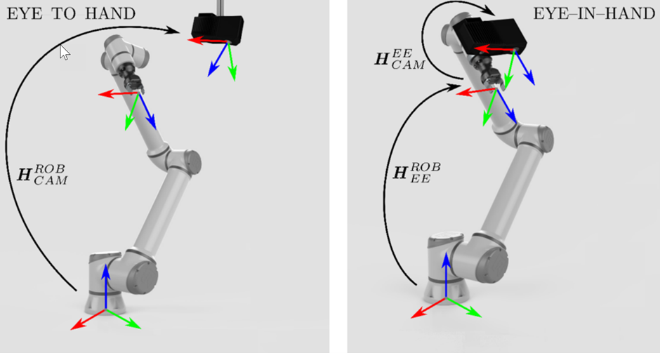 Fig 17: Eye-to-hand and Eye-in-hand calibration techniques
In this way, we have introduced a new ‘absolute’ reference point of the robot’s coordinate system, the calibration origin. Now the robot and 3D camera are in agreement about where the origin is, great, we’re in agreement and looking like having a system that relates to the same point to derive its accuracy.
We have two excellent guides explaining why hand-eye calibration is so important and how to perform a hand-eye calibration with Zivid cameras.
We hope you enjoyed part two of this series on trueness, it was a lot to get through, but well done, we’ve covered some important ground.
Want to get to the next level? Read the full technical white paper about precision, trueness, and accuracy:
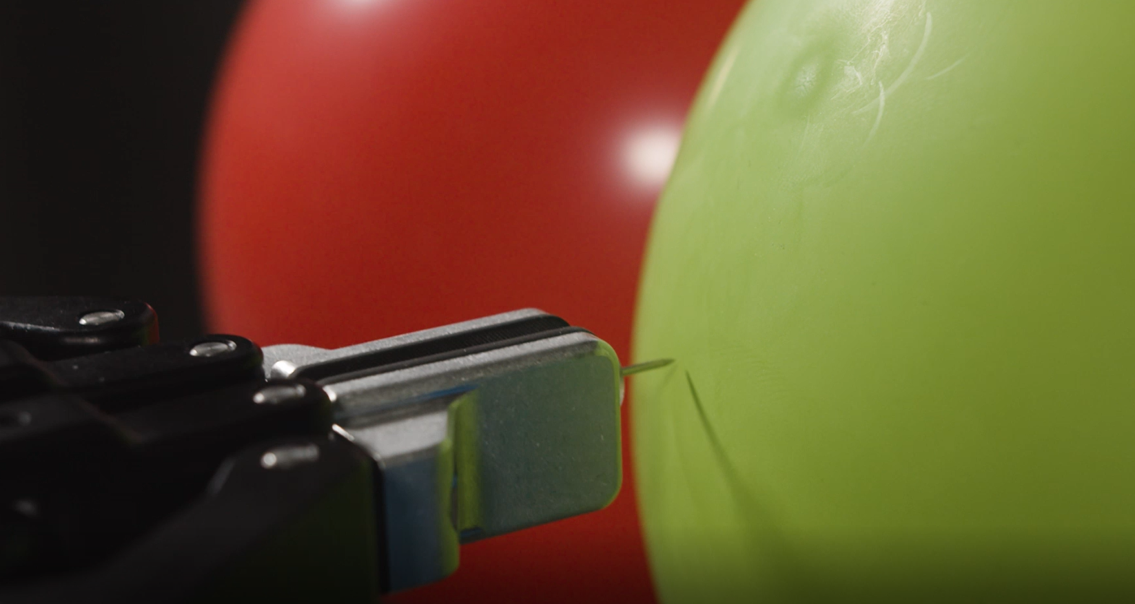
Test of Trueness: Balloon vs. Pushpin
Trueness - the missing metric in 3D imaging?