The Zivid cameras use a technique called structured light, where a projector and a camera are placed next to each other to shine a light on and take images of objects.
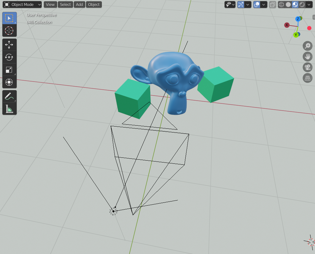
Soon after I started working for Zivid, I realized I wanted to understand how structured light can create detailed 3D images of objects. How does shining different patterns of light on objects tell us anything about their geometrical structure? To figure this out, I decided to create a simple test scene in Blender, with a camera and projector separated by a small distance.
Find the scene and source code for this post.
Setting up a basic projector and camera in Blender
The camera is just a regular Blender camera. The projector is made from light with an image as color input.
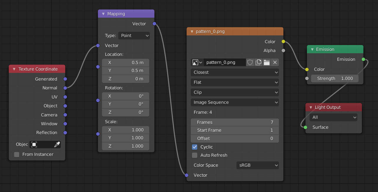
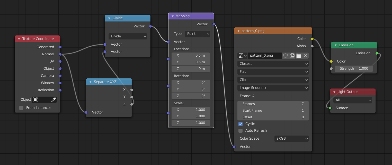
The image input to the light is done with Blender’s node system by connecting an emission node to the light output and an image node to the emission color. The vector input of the image needs to be set to the normal of the texture coordinate to determine which pixel of the image is chosen:
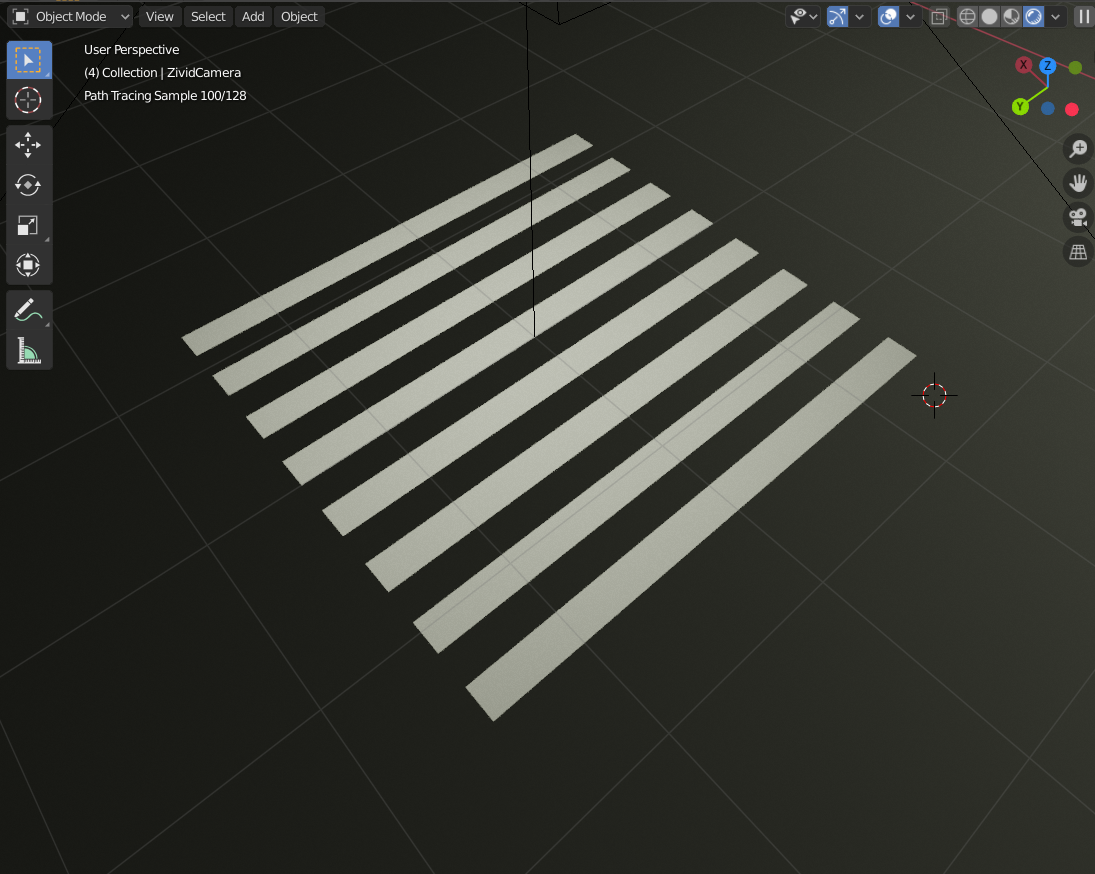
However, the projection comes out a bit distorted. Here it is shown projecting directly down on a plane:
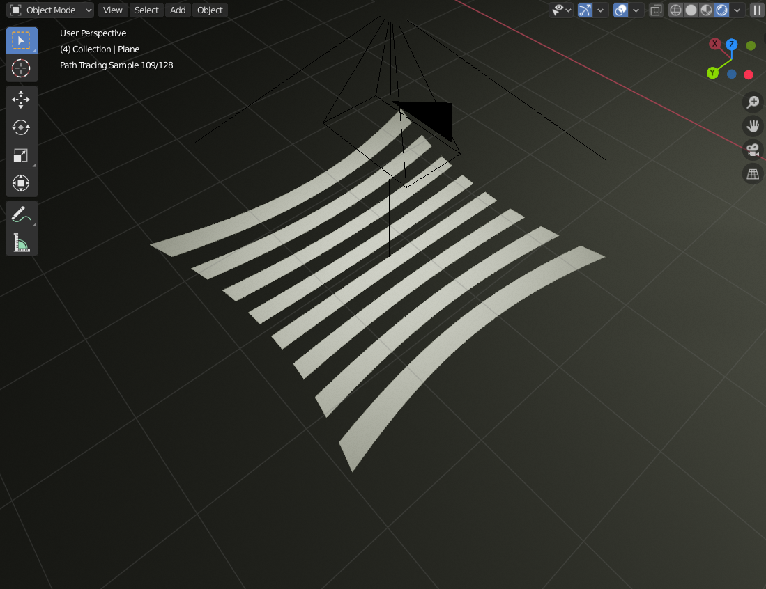
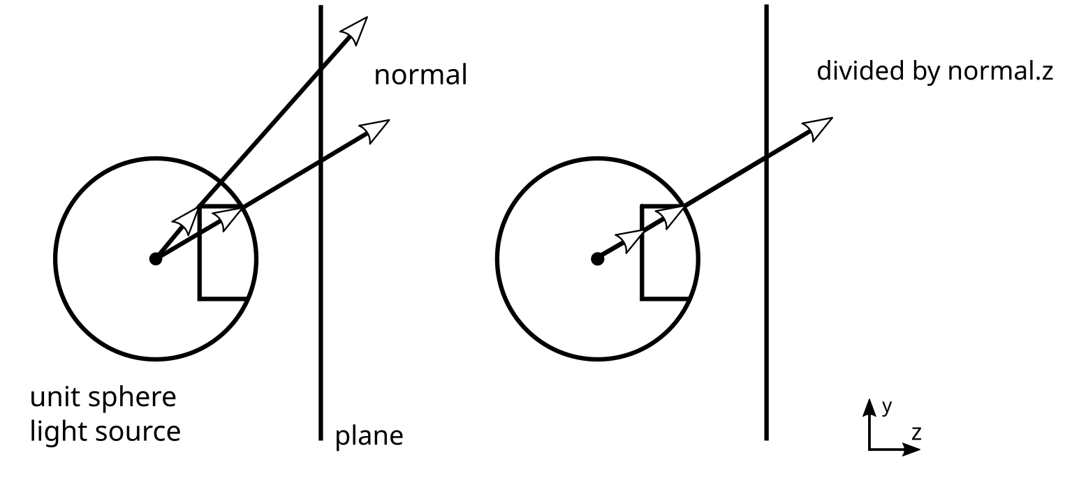
This issue occurs because the normals are projected from a unit sphere.
If you draw a line across a unit sphere for a given y-value and look at how they will be projected onto a plane screen, you will notice that the rays that hit the plane are at different y-coordinates on the plane. This is because they travel different distances before hitting the plane. To compensate for this, we can divide the normal of a ray hitting the plane by its z-value, which will give the rays the proper y-value in terms of what we want for the texture coordinates:
In our node setup in Blender, the division by z can be achieved by a vector separation node and a vector division operation:
And in turn, get something more like what we would expect from a real projector:
Of course, a real projector would have a lens with some defocus and distortion.
The projector I made in Blender is closer to an ideal pinhole projector: the projector equivalent of a pinhole camera. A perfect pinhole projector is okay for this project since I want something easy to work with to learn how structured light works - not how to solve all its real-life challenges.
The idea behind structured light
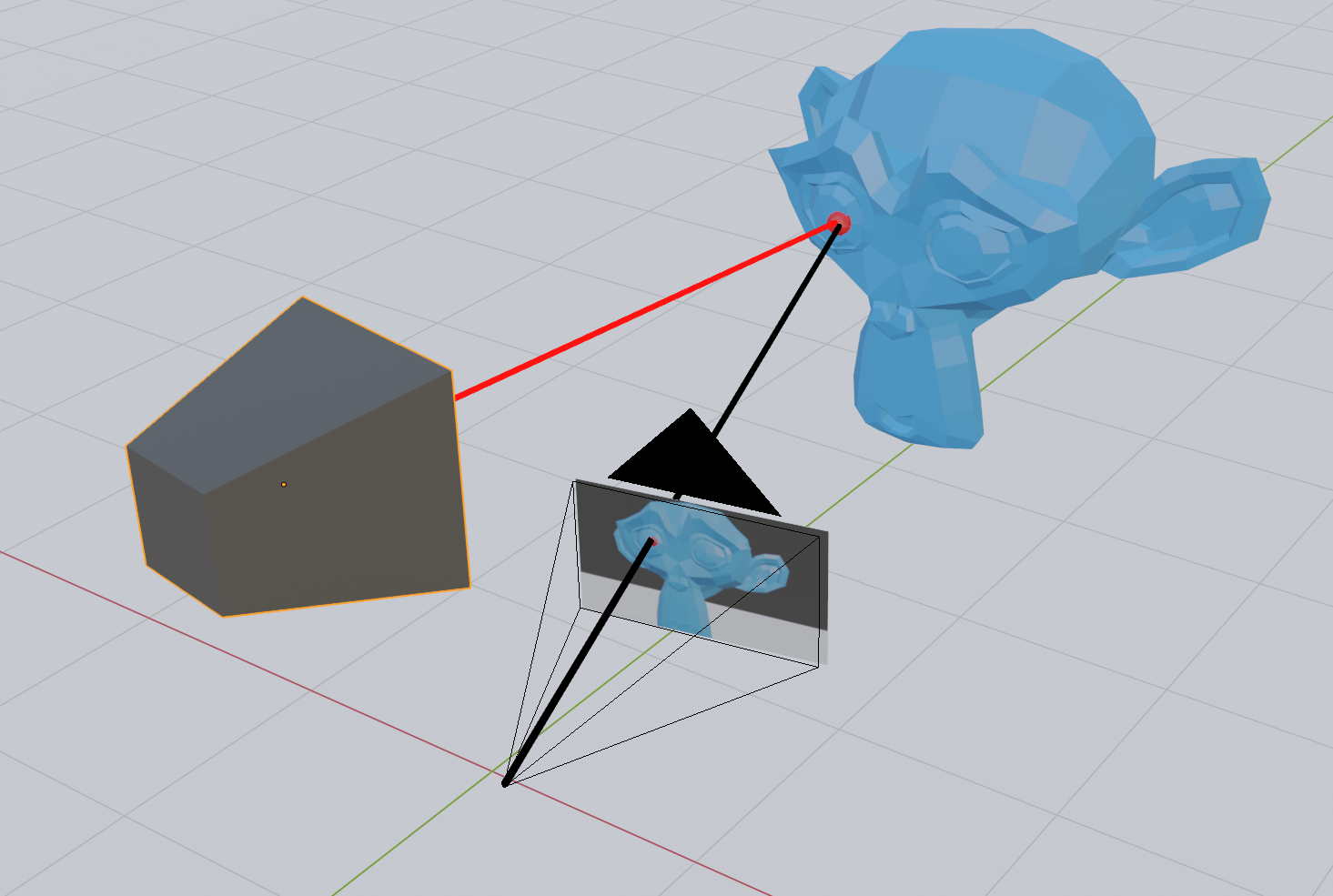
The way structured light enables robots to see in 3D is by taking advantage of the offset and angle between the camera and projector. This is similar to how our eyes make us able to see in 3D with stereo vision, which is also used in a number of 3D cameras.
Stereo vision works by taking one image from two regular cameras and finding standard features in both. If you can identify the same point in both images, you have enough information to determine the position of that point. At least relative to the camera.
Once a point is found in both images in a digital stereo camera, you have the pixel coordinate on both images. To find the 3D point, you can just draw a line from the focal point of each camera through this pixel coordinate and see where they intersect - or where they are closest to intersecting.
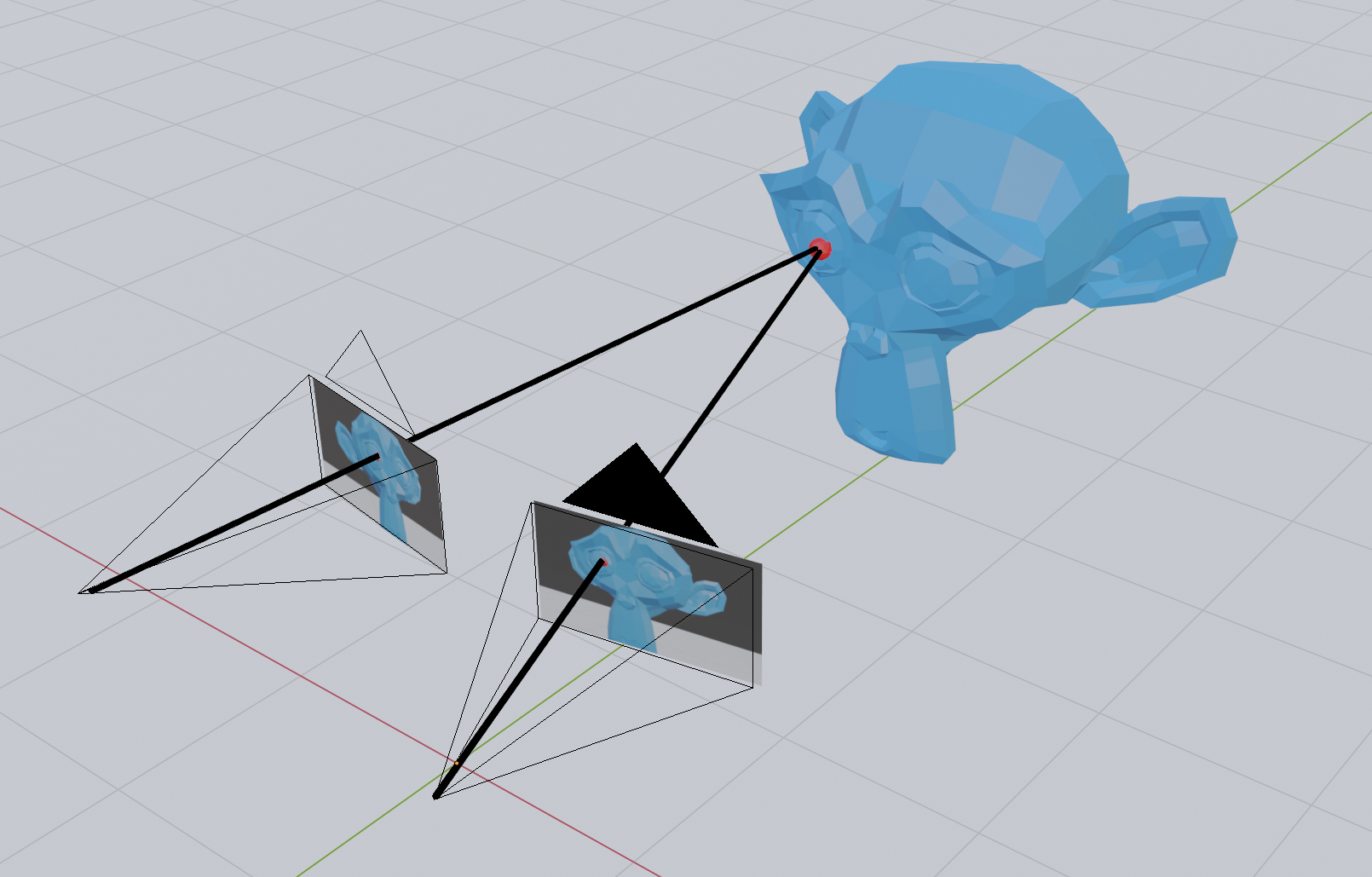
In structured light, one of the cameras is replaced by a projector. This allows us to skip the step where we detect common points in the two images since we can light up a single point with the projector and detect only that in the camera.
However, emitting light on each point this way will take a lot of time, since you would need to take one image for each pixel on the projector. With about two million pixels in the image, we are talking about hours of imaging with a camera capable of recording at 60 FPS. Instead, we can choose to light the scene with a few clever patterns that make use of some geometrical facts about our scene.
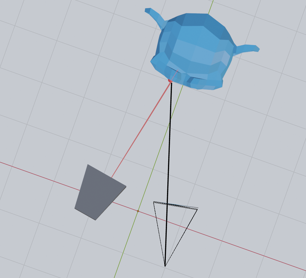
First of all, if we light the scene with horizontal lines, we may notice something peculiar when looking at the scene from the camera:
Now compare this with vertical lines:
Notice how the horizontal lines stay in the same place regardless of the position of the monkey mesh?
However, the pixel position of the vertical lines changes depending on the position of the monkey. I will try to get back to why this is in a later post, but the short story is that the horizontal lines do not move because the offset between the camera and projector is itself horizontal.
Every horizontal line on the projector corresponds to a so-called epipolar line on the camera.
Based on this observation, we will, for now just assume that horizontal lines provide us with no information about the depth of the object we are imaging, while vertical lines do. In other words, it appears as if the only interesting property we need from the projector is the x position of the pixel. With the x-coordinate on the projector, we can create a plane that intersects with the camera line. The information that we get from the y-coordinate of the projector pixel must be already be contained in the y-coordinate of the camera pixel.
A line-plane intersection strategy
Since there is no additional information in the y-coordinate of the projector pixel, we can find the 3D position of a point seen in the camera by intersecting the line from the camera pixel with the plane corresponding to an x-coordinate on the projector.
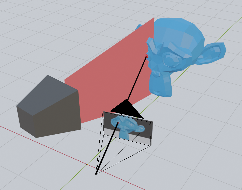
This means that given a pixel on the camera, all we need is some way to use the color of that pixel to determine the x-coordinate on the projector. With the x-coordinate on the projector, we can create a plane that intersects with the camera line.
The binary code patterns
There are a number of ways of encoding the x-coordinate of the projector in the pixel of the image.
If we were looking at a completely white scene, we could use the color of the projector pixel to code for a specific x-coordinate. However, with colored objects in the scene, we might lose some information if the color is not projected back to us correctly.
We can also take two images and use the diff to encode the information we need, but again this might be hard with colors if the objects in the scene absorb entirely the colored light we use for encoding.
A third option is to take multiple images with several completely black-and-white patterns. The simplest option is perhaps to use a binary pattern, which when read back can be interpreted as the x-coordinate on the projector. They consist of seven images with black-and-white areas:
.png?width=800&name=MicrosoftTeams-image%20(5).png)
The binary code for a pixel in an image is found by first calculating the minimum and maximum value for the same pixel across all images. Then we compare the pixel value of a given image with the average of the minimum and maximum values across all images. If a pixel in an image is brighter than the average, we set the value of that pixel. Otherwise, we assign it a zero.
Finally, we convert the binary code to a decimal number to obtain the x-coordinate on the projector:
We see that the patterns are not overlapping correctly, and we get a few black lines in the image, but overall this is good enough to continue.
Going from pixels to points
To calculate the intersection between the line coming from the camera pixel with the plane corresponding to the projector x-coordinate, we first need to set up a few matrices that can take us from a pixel to a point. For this purpose, I will use the conventional 4x4 matrices used in computer graphics. Thankfully, these are pretty easy to set up using existing linear algebra libraries such as Eigen and glm.
Intersecting camera rays with projector planes
Now that we are able to go from camera pixels to points in 3D space, we can create a line through our camera pixel. We, of course, do not know the z-value of our pixel, but by guessing two values and pulling a line through the corresponding points, we get our camera line.
This line can then be intersected with a plane that is parallel with the y-axis and going through the projector x-coordinate. If we look at this in 2D, this is just a simple line-line intersection.
We can, therefore, calculate a 2D line intersection to find where along the camera line the 3D intersection happens.
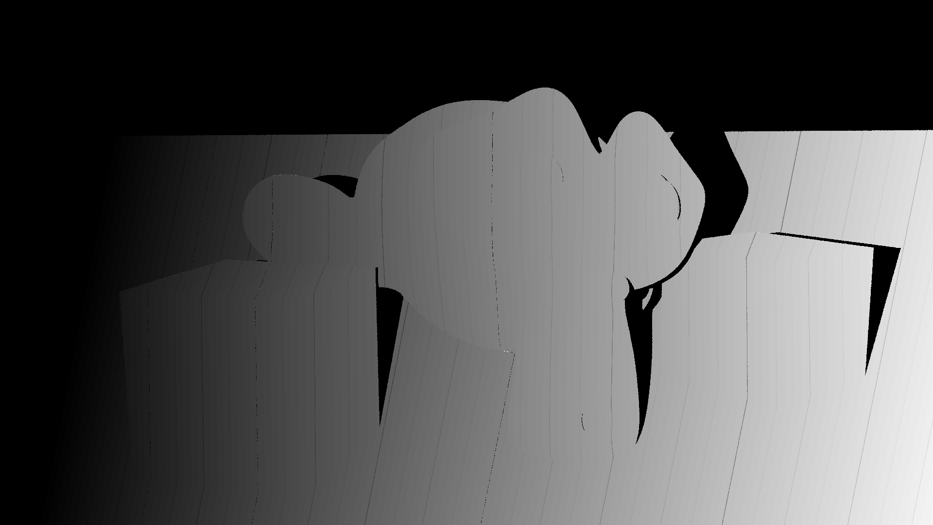
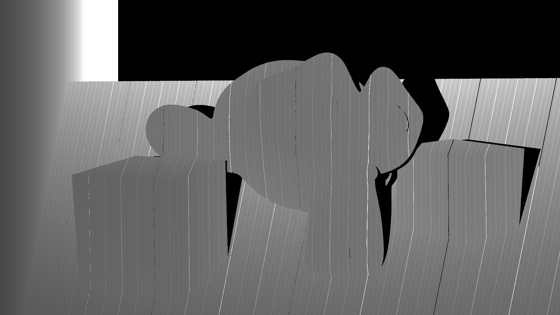
We can then save the z value to an image. Note that the z-value is negative in the matrix convention we have used and that I divide by 3.0 because I know that better reflects the distance to the objects in the scene. The resulting depth image looks as follows:
But what we want is not just the depth as an image. We want to produce a 3D model from the images.
To produce the 3D model, we can create a new function to store the x, y, and z values together with the color. The color can be calculated as the mean of the maximum and minimum colors in the images. The average is between the color we would see when the projector lights the entire scene and when there is no light from the projector.
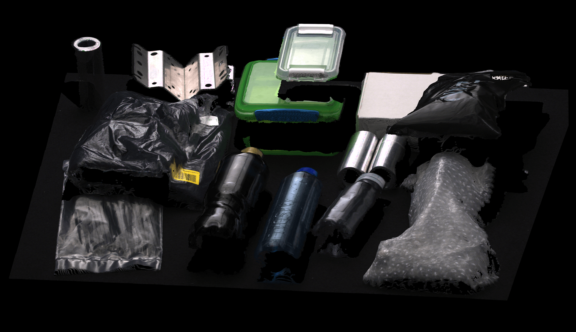
The XYZ file is loaded in a viewer:
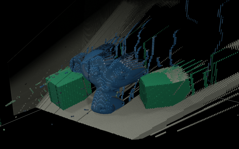
After looking at some really bad results for a day when I had the wrong matrices, I was really happy to get this on screen!
Sure, there is still a lot of noise to clean up and weird effects such as the floor, which now has a thickness, but I will address those later.
For now, I am happy with this as it is.
Do you want to read the full article with code examples?
The new 3D vision tools enabling bin-picking automation

Stop point cloud artifacts